Co based alloy additive manufacturing

Metallographic preparation of additive manufactured parts

As a recent production technique, additive manufacturing presents new challenges for the professional materialographer. Written in collaboration with the Danish Technological Institute (DTI), this paper details proven methods for preparing additive manufactured parts for materialographic analysis quickly and accurately.

Download the full application note

What is additive manufacturing?

Also known as 3D printing, additive manufacturing refers to technologies that grow 3D objects one superfine layer at a time. Each successive layer bonds to the preceding layer of melted or partially melted material to create components, parts, or complete products.

The benefits of additive manufacturing
Additive manufacturing simplifies the design and creation of complex components as a single object, thus reducing time and cost when building models and prototypes. It is growing as a serial production method, particularly of complex parts, for many reasons:
  • Design improvements: Integrate multiple parts into one object in the design phase, which allows for improved strength, less weight and increased durability.
  • Cost savings: Reduced material wastage, tool costs and labour requirements are driving manufacturing costs down for AM.
  • Lead time reduction: Manufactured parts can be ready to use right out of the machine or with limited post processing.
The characteristics of additive manufacturing materials
Initially the metals available for additive manufacturing were connected to the industries driving the development, the automotive, aerospace, and medical industries. However, multiple new and redeveloped alloys keep entering the market. In general, additive manufactured parts have the same or better mechanical properties and densities than traditional manufactured parts. The most common defects and deviations related to additive manufacturing can be categorized into these three groups:
  • Surface quality: Without post-processing, additive manufactured parts have high surface roughness.
  • Geometry and dimension deviation: Thermal shrinkage due to cyclic heating may lead to dimensional deviations.
  • Microstructure defects: Porosities can be an issue, typically caused by gas or a lack of fusion.

Manufacturing tools and aids


Fig.1: Manufacturing tools and aids

The production of additive manufactured parts

There are seven main types of additive manufacturing processes defined by ISO/ASTM 52900:2017. This application note focuses on parts made using one specific technique: Laser Powder Bed Fusion (L-PBF (Laser Powder Bed Fusion)).

The L-PBF process
A fine metal powder of spherical particles (15-60 μm in diameter) is spread evenly across a base platform. A laser scans across the powder, heating and welding it together and to the layers below. This repeats until the final component is finished.

Destressing
After the build process, the parts are often destressed in a gas protected environment. If not, some materials and geometries will crack or deform when they are cut from the build plate.

Heat treatment
The finished part has a very fine microstructure that has cooled rapidly, usually resulting in high-strength and low-ductility. Heat treatment may be used to tailor the part to specific mechanical properties or increase corrosion resistance.

There are several parameters in the manufacturing process that affect material quality and characteristics.

Find more information in the full application note.

Rocket Nozzle for a student project


Fig. 4: Rocket Nozzle for a student project.

Materialography of additive manufactured parts

Additive manufactured components can be found in a wide range of applications. This includes critical applications, such as torsion springs and brake calipers on cars, fuel nozzles and turbine blades on jet engines, and medical implants.

As a result, metallographic examination of additive manufactured components is common for quality control. In general, this is performed on feedstock powders or test/target specimens.
  • Feedstock powders: Powders are investigated for particle size distribution, shape, or structure.
  • Representative specimens: These are small rods or cubes printed alongside the additive manufactured part to enable microstructural analysis of the material without breaking the part.
As many different metals and alloys are used in additive manufacturing, there is no single methodology for metallographic preparation. In general, the preparation should be the same or similar to standard preparation methods used for other parts or components made of the same material.

Download the full application note to get a detailed description of the materialography of additive manufactured parts.

Cutting and mounting of additive manufactured parts

Recommendations for mounting feedstock powders
  • To examine the particle size distribution, it is recommended to make a longitudinal cut through the cured mount and remounting it at an angle of 90°.
  • Hot mounting of powders is possible but requires resin without metallic fillers, unless additional etching can be used to distinguish the powder from the resin.
  • Cold mounting in epoxy is recommended. If you are working with small-sized or lightweight powder, it can be useful to heat the resin to make it easier for the powder to sink.
Recommendations for cutting and mounting of test/target specimens
  • The build-up/layering direction must be taken into consideration when cutting, depending on the purpose of the analysis.
  • As additive manufactured test specimens are generally small, precision cutting solutions with reliable clamping tools are preferred.
  • If specimens are very small or the geometry complex, then they can be mounted in transparent epoxy (EpoFix or CaldoFix-2) before cutting to avoid damaging the specimens.
  • Both hot mounting and cold mounting are possible. Cold mounting is recommended if specimens are fragile, very small or have a complicated shape.
You can find a more detailed description of how to cut and mount additive manufactured specimens in the full application note.


Find out more

Metallic steel powder stirred

Figure 9. Metallic steel powder stirred in FixiForm with CaldoFix-2 (left). Polished and etched with modified Klemm etchant (right). Bright field.

Cross section through a mount

Figure 10. Cross-section through a mount with AlSiMg10 powder in EpoFix, remounted. The polished specimen shows the microscopic distribution, size, and shape of powder material (bottom).

Tablets of metallic powder

Figure 11. Tablets of metallic powder enriched PolyFast, pressed in CitoPress and glued temporarily on a MultiFast dummy specimen (left). Tablet glued on metal support block (middle), for later investigation in a SEM. Microscopic image of steel powder particles in PolyFast (right). Bright field.

Longitudinal

Figure 13. Longitudinal (left) and cross section (right) of AlSi10Mg alloy, etched with Fuss etchant. Bright field.

Grinding, polishing & etching of additive manufactured parts

When working with additive manufactured specimens, the grinding, polishing and etching stages of preparation vary greatly, depending on the material/alloy. Here are brief recommendations for four common materials used in AM.
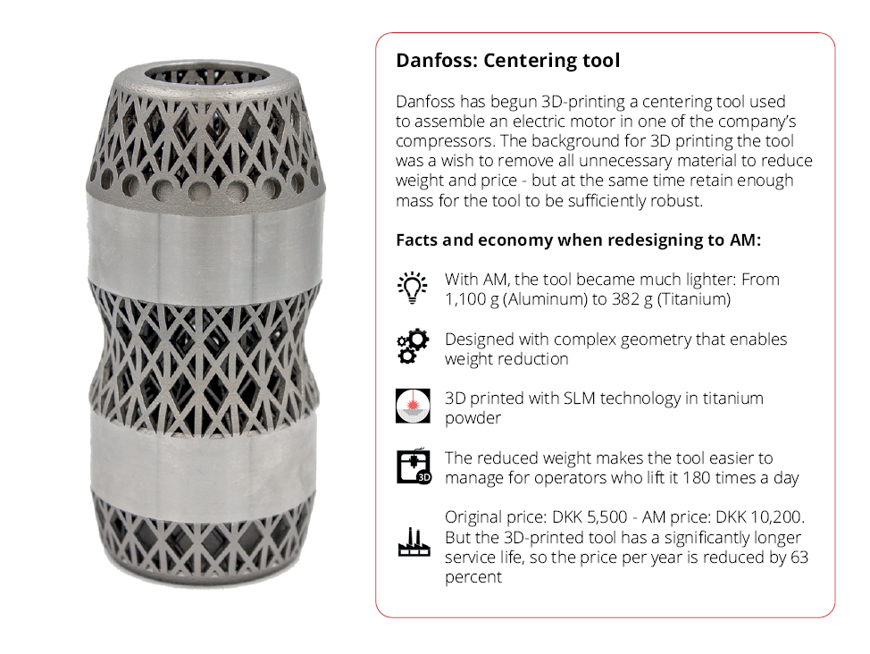
Titanium
In general, preparation should follow the standard methods used for other titanium specimens.
  • Due to its high ductility, titanium is prone to mechanical deformation and scratching. Diamond polishing should be avoided, especially with pure titanium.
  • For less alloyed titanium, electropolishing is recommended.
  • To reveal more information, etching is often required after mechanical or electrolytic preparation. As titanium is chemically resistant, etchants containing hydrofluoric acid are recommended.
  • Polarized light is an excellent optical etching method for titanium.

Table

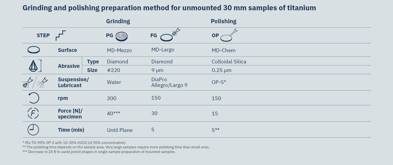
Table 2. Grinding & polishing preparation method for unmounted 30 mm samples of titanium.

See the full application note for detailed descriptions and proven methods for polishing, electropolishing and etching of titanium additive manufactured specimens.

Final polished titanium

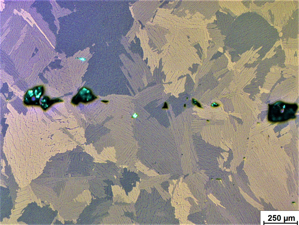
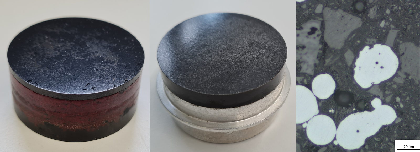
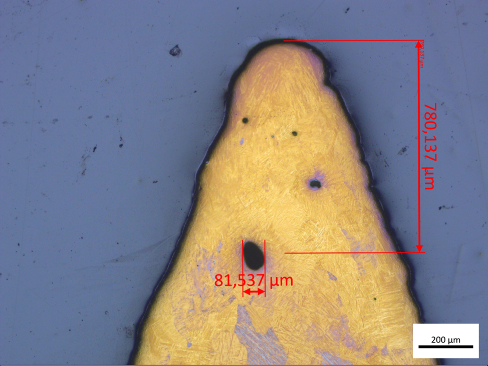
Figure 14. Final polished titanium specimen with pores. Polished on MD-Chem with OP-S NonDry and additive, with a visible microstructure in polarization contrast.

Titanium alloy

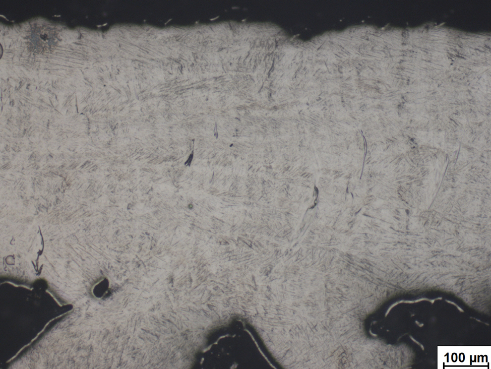
Figure 15. Titanium alloy. Electrolytical preparation with A3, not mounted. Bright field.

Titanium alloy

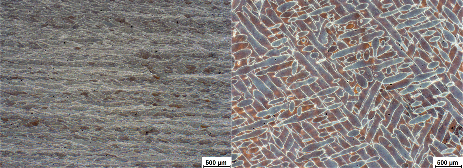
Figure 16. Titanium alloy. Electrolytically polished and chemical etched with Fuss etchant. Bright field.

Titanium alloy

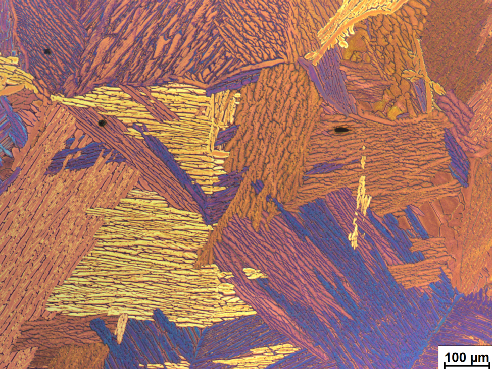
Figure 17. Titanium alloy after etching with Keller etchant. Polarized light.
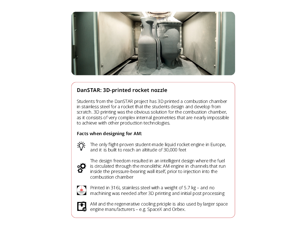
Aluminum
Although aluminum is soft, alloying elements can significantly change its mechanical properties. In general, preparation of additive manufactured specimens should follow the methods used for similar aluminum specimens.
  • To avoid deformation, scratching and edge rounding, it is recommended to use a rigid plane grinding surface specifically developed for aluminum alloys, called MD-Molto.
  • When fine grinding, MD-Largo with diamond suspension (e.g., DiaPro Allegro/Largo) is suitable for many types of aluminum.
  • To ensure thorough polishing, follow the fine grinding with a diamond polishing (MD-Mol) and an oxide polishing (colloidal silica, OP-U) steps.
  • To reveal more or specific details, chemical, electrolytical, and optical etching methods, or a combination, can be used.

Table

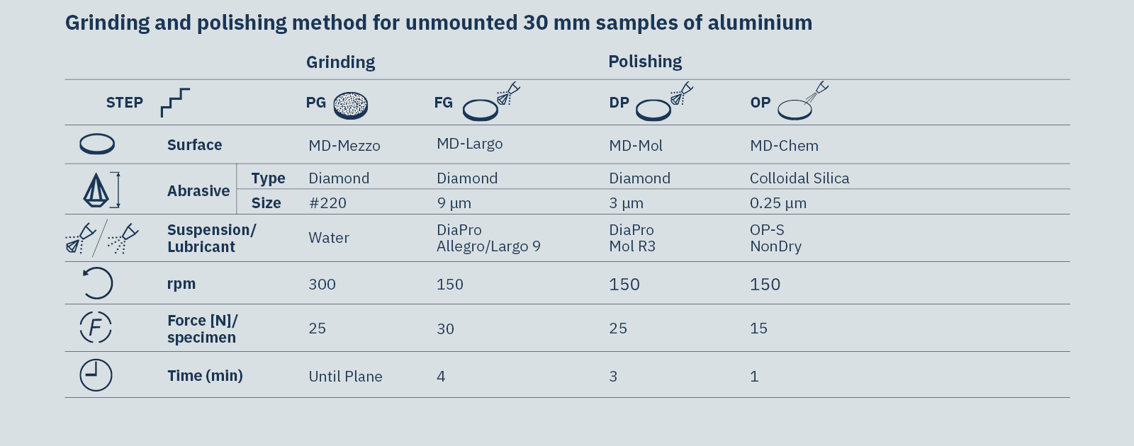
Table 3. Grinding & polishing method for unmounted 30 mm samples of Aluminium

For more detailed information and methodology, see the full application note.

Different aluminium alloys

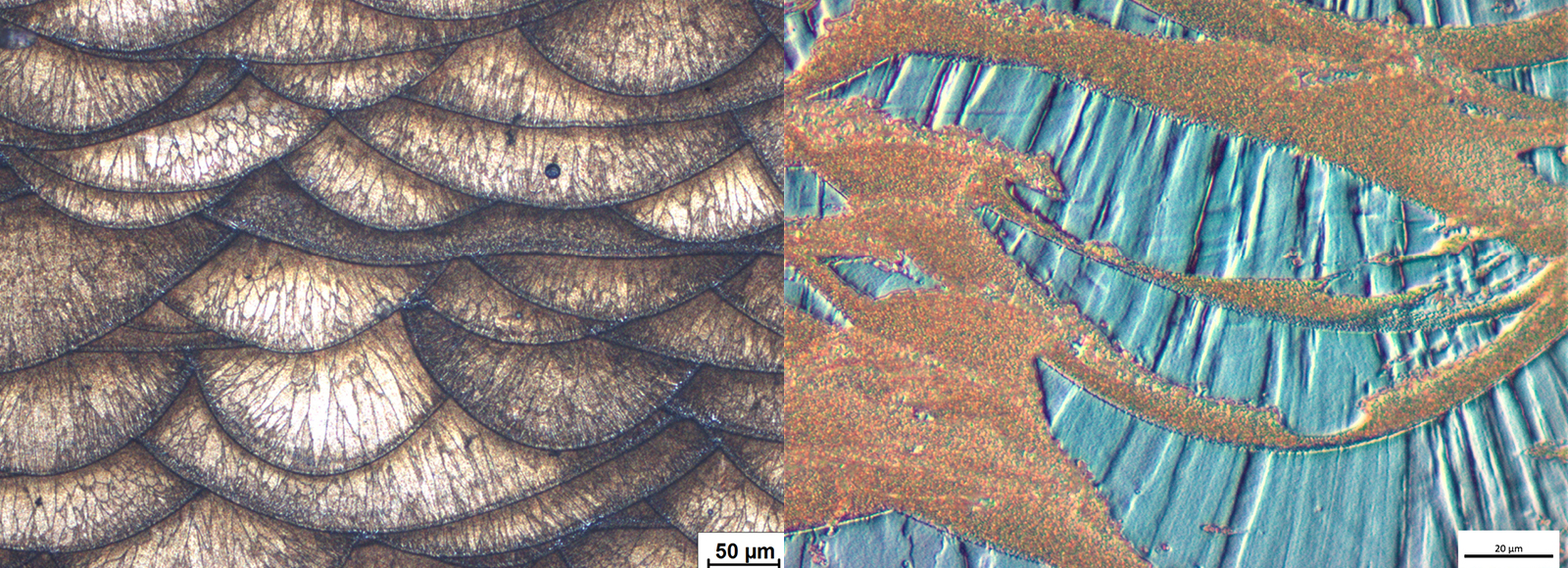
Figure 18. Different aluminium alloys after Barker‘s etching in bright field (left) and in differential interference contrast, DIC, (right).

Fine polished surface

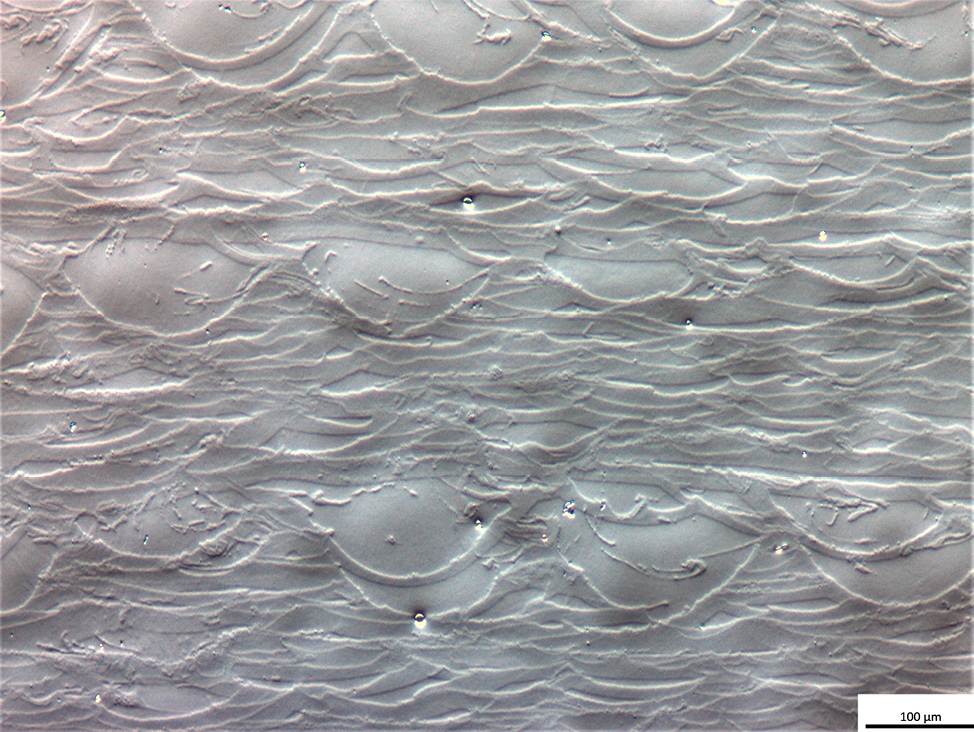
Figure 19. Fine polished surface of aluminium alloy. Polished with MD-Chem and OP-S. Differential interference contrast, DIC, unetched.

Overview of aluminium alloy

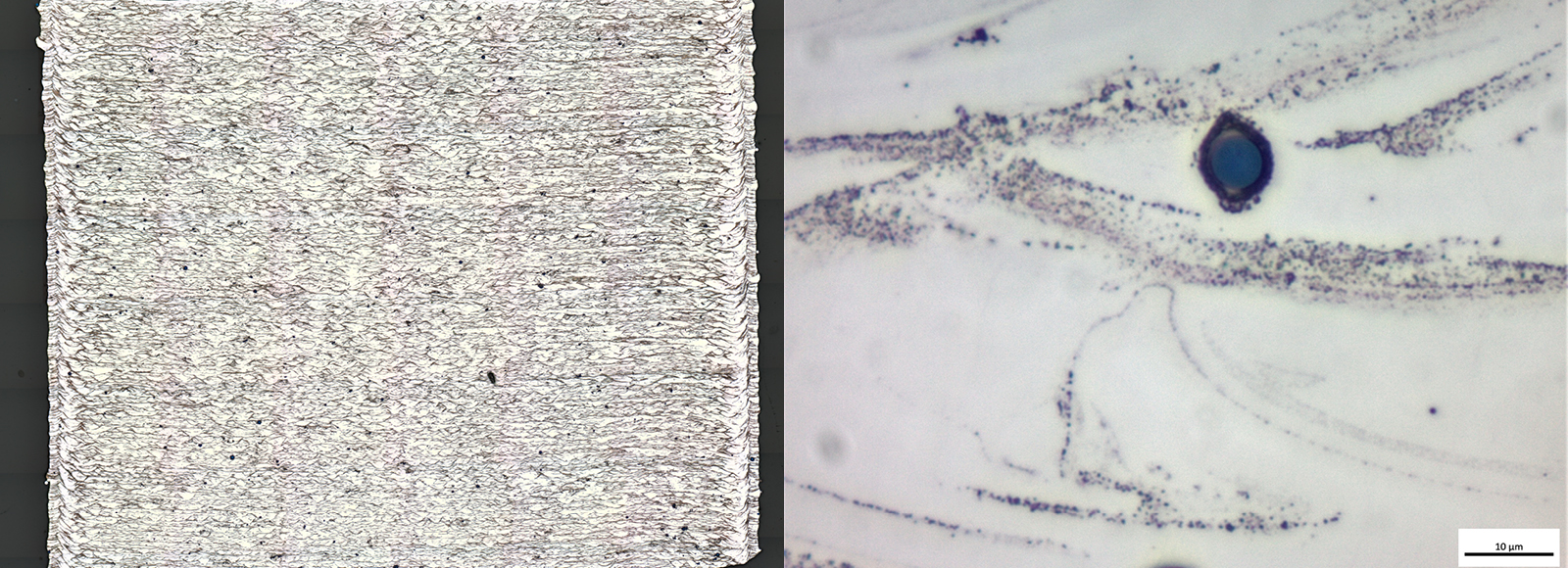
Figure 21. Overview of aluminium alloy, etched with Barker’s (left). Detail of aluminium alloy, with precipitation in high magnification (right). Bright field.

Aluminium alloy after Barker s

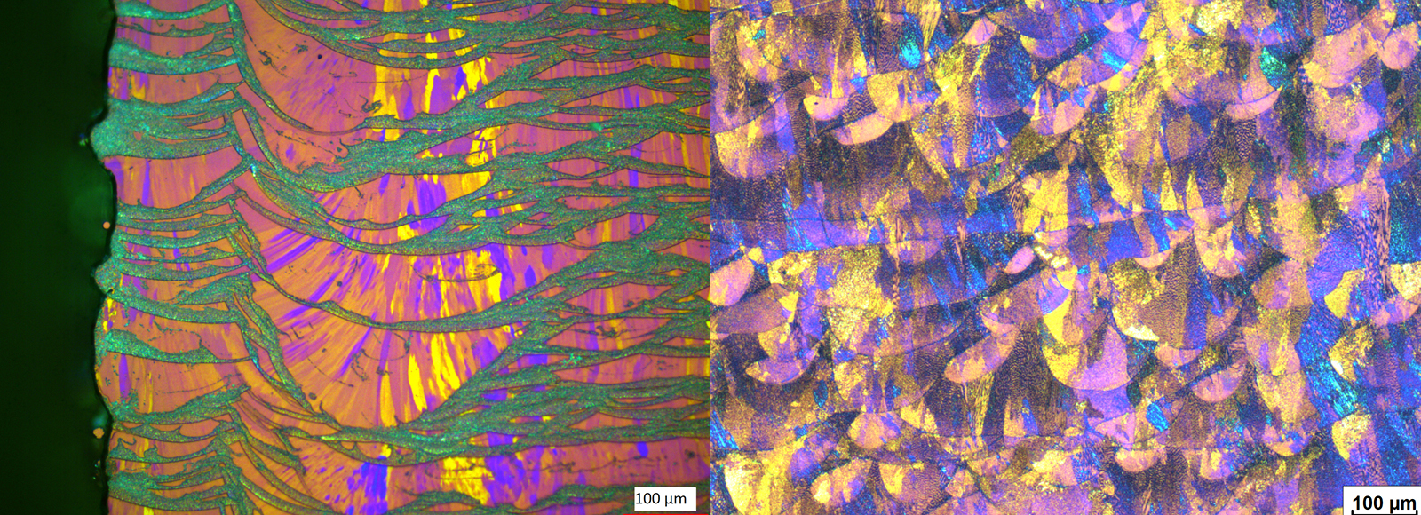
Figure 22. Aluminium alloy after Barker’s etching (left). Inconel etched with Adler (right). Polarized light.

Stainless steels and nickel-based alloys
As these materials are often soft and ductile, very coarse grinding surfaces and high pressure should be avoided. In general, the preparation should follow the standard methods used for other stainless steels and nickel-based alloys.
  • Use a dedicated plane grinding disc, such as MD-Alto.
  • Fine grinding should be carried out with diamond suspension on a rigid disc (MD-Largo) or MD-Plan cloth.
  • Follow fine grinding with a thorough diamond polish on a medium/hard cloth (MD-Dac).
  • We recommend a final polish with colloidal silica (OP-S) or alumina (OP-A) to remove any fine scratches.
  • Electrolytic etching with 10 % oxalic acid in water is common. However, for duplex steels, electrolytic etching with NaOH (20 % in water) delivers better results.

Table

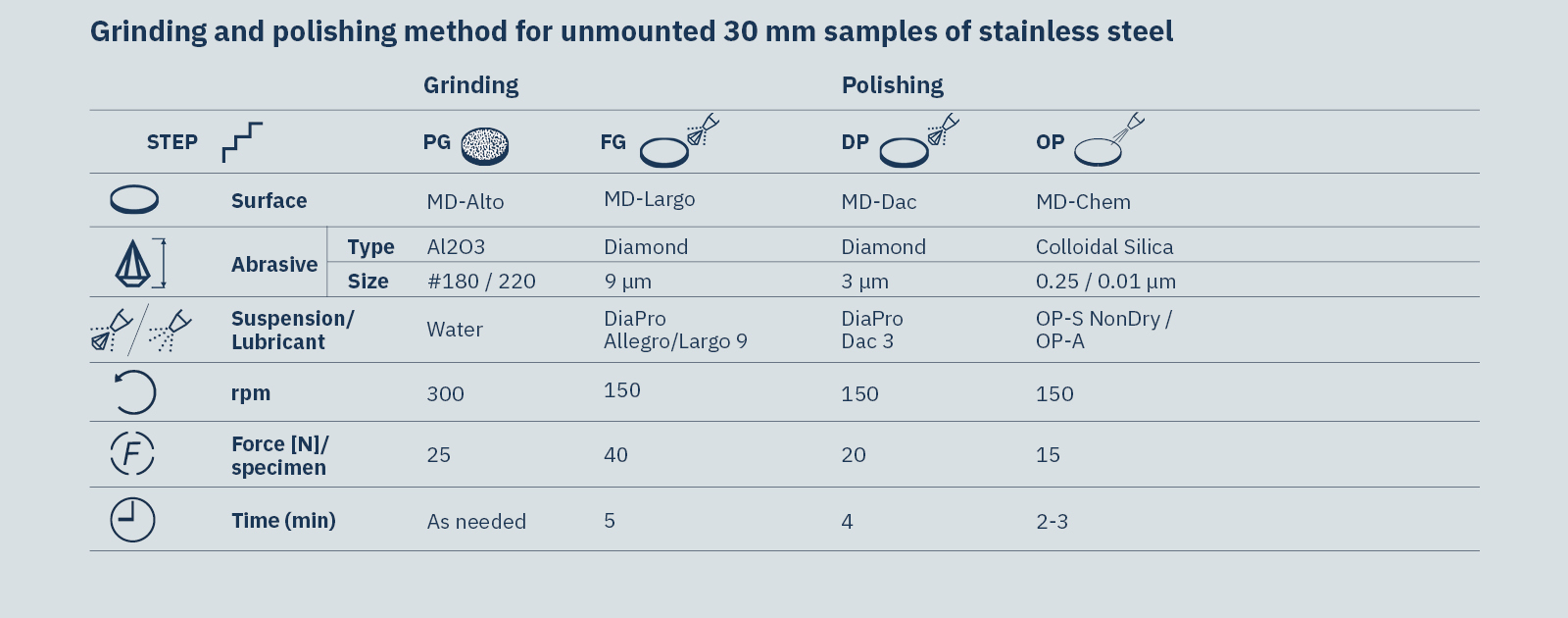
Table 4. Grinding & polishing method for unmounted 30 mm samples of Stainless Steel

For more detailed information and methodology, including how to prepare specimens for porosity evaluation, see the full application note.

Austenitic steel after polishing

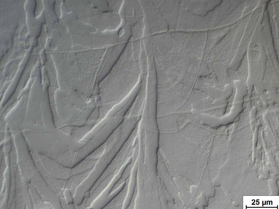
Figure 24. Austenitic steel after polishing with OP-S on MD-Chem. Structure visible without chemical etching. Differential interference contrast, DIC.

Inconel 718

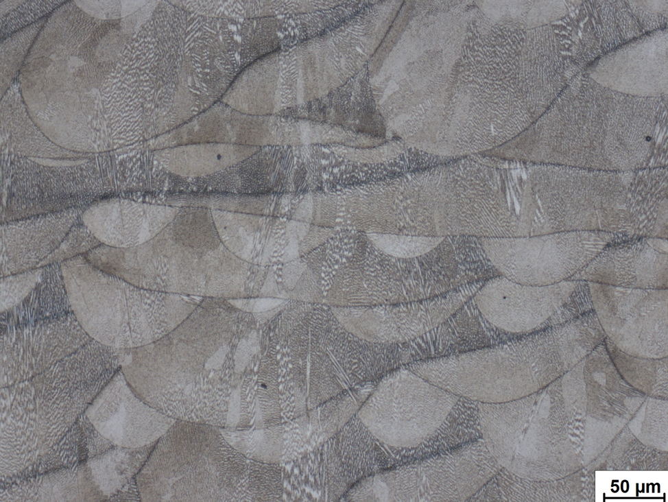
Figure 25. Inconel 718, etched with Adler etchant. Bright field.

Duplex steel 14462

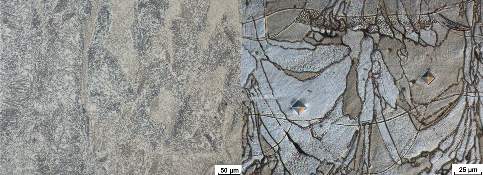
Figure 26. Duplex steel 1.4462 after electrolytic etching with oxalic acid (10%). Bright field (left). Duplex steel 1.4410 with micro hardness indents, after electrolytical etching with 20 % NaOH in water. Differential interference contrast, DIC (right).

Tool steels
Tool steel is made with large amounts of alloying elements, such as chromium, nickel, vanadium, or molybdenum. The main challenge when grinding and polishing is ensuring that carbides and non-metallic inclusions are retained. In general, preparation should follow the standard methods used for other tool steels.
  • For plane grinding, it is recommended to use plane grinding discs with embedded diamonds (MD-Piano).
  • For fine grinding, use a metal bonded diamond disc (MD-Allegro) with diamond suspension.
  • For highly alloyed steels, it is possible to use Klemm etchant.

Table

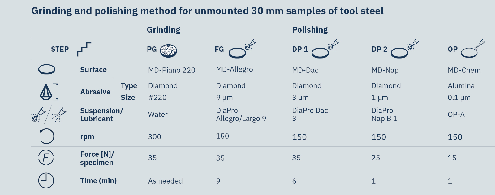
Table 5. Grinding & polishing method for unmounted 30 mm samples of tool steel

See the full application note for more detailed information and methodology.

Tool steel 12709

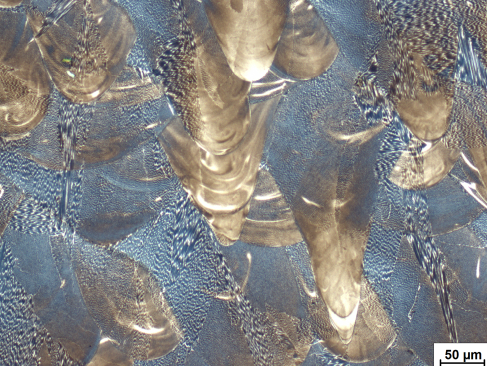
Figure 27. Tool steel 1.2709 after etching with modified Klemm (10/3) and addition of HCl.

Find out more

Target preparation

With additive manufactured specimens, it is often important to investigate microscopic attributes in the microstructure. These targets include pores, cracks, or inclusions from laser sintering, as well as impurities from different feedstock materials.

When visualizing porosity and cracks open to the surface, epoxies with fluorescent powders are a useful solution. We recommend:
  • Heating up the epoxy to 50-60°C to increase viscosity.
  • Using active cooling during curing to improve impregnation and lower shrinkage and gap formation.

The use of fluorescent dye with this technique requires a special feature in the microscope.

See the full application note for more detailed information.

Filling of a crack in an aluminium

Figure 28. Filling of a crack in an aluminium alloy with fluorescent resin (left). Open porosity in austenitic steel (right).

Contamination of AlSi

Figure 29. Contamination of AlSi powder particle in CuCrZr1 specimen. Bright field.

Light microscrope

Figure 32. Light microscope image of large pore in a titanium alloy. The specimen was etched with 100 ml water, 10g NaOH and 10 ml H2O2.

The materialography of additive manufactured parts

Additive manufacturing is one of the newest and fastest growing component manufacturing techniques. Although primarily used for the creation of prototypes and one-off designs, it is increasingly being used in general manufacturing to produce high-strength and lightweight single-component parts with complex geometries.

As a relatively ”young” production technique, additive manufacturing presents new challenges to the professional materialographer. In general, materialographic investigation is performed on feedstock powders or representative test specimens as part of quality control. These specimens are often very small, so high precision cutting and clamping equipment is recommended.

Many different metals and alloys can be used in additive manufacturing. As a rule of thumb, preparation should be similar to standard preparation methods for that material. However, methodology may differ, depending on the specific specimen.

In the full application note, you can find a detailed description of how to prepare additive manufactured parts for materialographic analysis. As well as a comprehensive description of the general challenges and solutions, the application note includes proven methods and techniques for different additive manufactured materials and alloys.

Download the full application note

Get insight into other materials


If you would like to learn more about the materialography of other metals and materials, check out our materials page.

Holger Schnarr

All images by Ólafur Ólafsson, Application Specialist, Denmark.

For specific information about the metallographic preparation of Additive Manufacturing:

Contact our application specialists.